型号:MCU-122
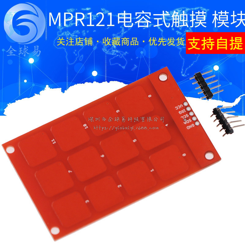
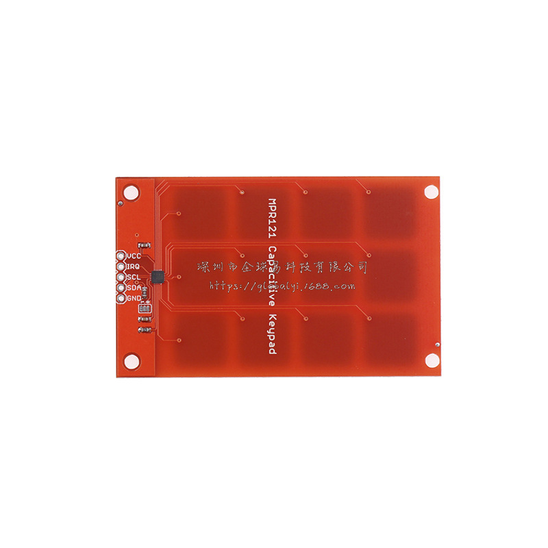
MPR121模块 电容式 触摸 传感器 按键 感应按键 键盘
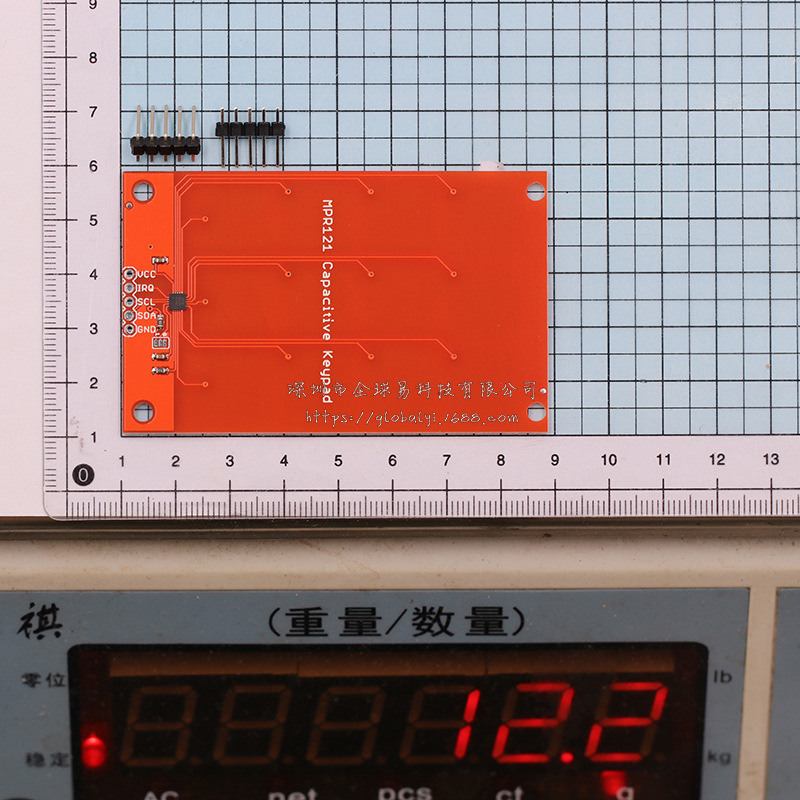
尺寸:48mm*78mm
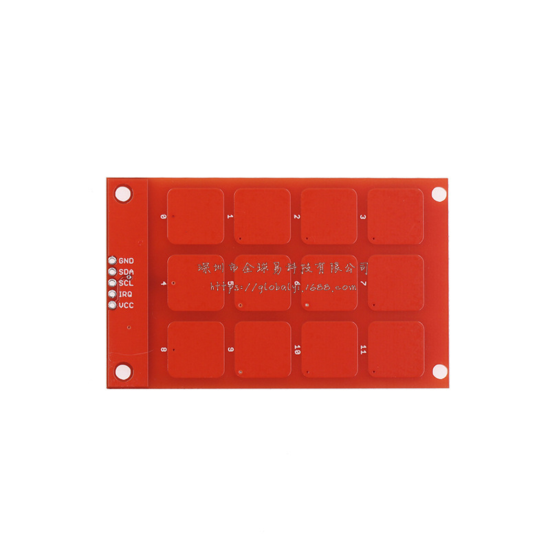
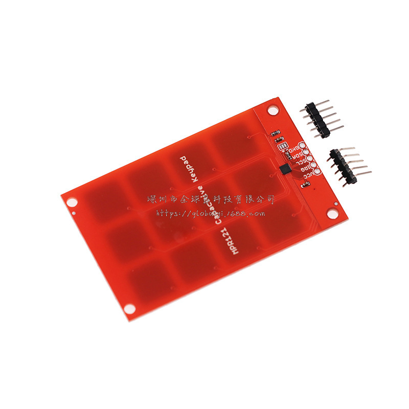
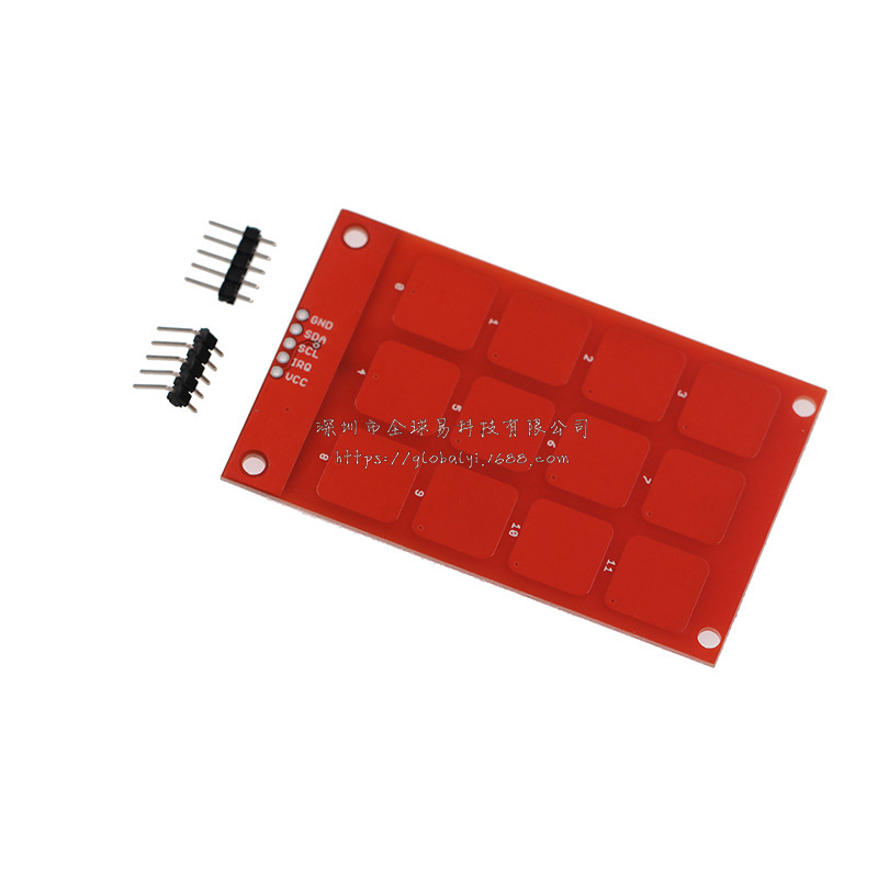
Description: The MPR121 capacitive keypad uses the MPR121 and 12 touch sensitive pads to give you a simple 'keypad' with an I2C output. The board also has four mounting holes allowing it to be used as an input system in place of traditional buttons. Check the example code below for an easy way to read the keypad. cjmcu.
Note: This keypad outputs 3.3V logic. If you are using a board which only accepts 5V logic, you will run into a problem. You will want to use a logic level converter, or a board which accepts 3.3V logic.
===================================================================
/* MPR121 Keypad Example Phone Dialing Code
by: Jim Lindblom
SparkFun Electronics
created on: 1/6/10
license: CC-SA 3.0
Turns the MPR121 Touchpad into a phone keypad. Pressing a pad will
print a 0-9, * or #.
Hardware: 3.3V Arduino Pro Mini
SDA -> A4
SCL -> A5
IRQ -> D2
I wasn't having any luck using the Wire.h library, so I've adapted
I2C code from an ATmega328 library to get this working.
If you can get this working with the Wire.h library, I'd be thrilled to hear!
*/
#include "mpr121.h"
#include "i2c.h"
#define MPR121_R 0xB5// ADD pin is grounded
#define MPR121_W 0xB4// So address is 0x5A
#define PHONE_DIGITS 10 // 10 digits in a phone number
// Match key inputs with electrode numbers
#define STAR 0
#define SEVEN 1
#define FOUR 2
#define ONE 3
#define ZERO 4
#define EIGHT 5
#define FIVE 6
#define TWO 7
#define POUND 8
#define NINE 9
#define SIX 10
#define THREE 11
int irqpin = 2; // D2
uint16_t touchstatus;
char phoneNumber[PHONE_DIGITS];
void setup()
{
pinMode(irqpin, INPUT);
digitalWrite(irqpin, HIGH);
Serial.begin(9600);
DDRC |= 0b00010011;
PORTC = 0b00110000; // Pull-ups on I2C Bus
i2cInit();
delay(100);
mpr121QuickConfig();
}
void loop()
{
getPhoneNumber();
Serial.print("\nDialing... ");
for (int i=0; i
Serial.print(phoneNumber[i]);
while(1)
;
}
void getPhoneNumber()
{
int i = 0;
int touchNumber;
Serial.println("Please Enter a phone number...");
while(i
{
while(checkInterrupt())
;
touchNumber = 0;
touchstatus = mpr121Read(0x01) << 8;
touchstatus |= mpr121Read(0x00);
for (int j=0; j<12; j++) // Check how many electrodes were pressed
{
if ((touchstatus & (1<
touchNumber++;
}
if (touchNumber == 1)
{
if (touchstatus & (1<
phoneNumber[i] = '*';
else if (touchstatus & (1<
phoneNumber[i] = '7';
else if (touchstatus & (1<
phoneNumber[i] = '4';
else if (touchstatus & (1<
phoneNumber[i] = '1';
else if (touchstatus & (1<
phoneNumber[i] = '0';
else if (touchstatus & (1<
phoneNumber[i] = '8';
else if (touchstatus & (1<
phoneNumber[i] = '5';
else if (touchstatus & (1<
phoneNumber[i] = '2';
else if (touchstatus & (1<
phoneNumber[i] = '#';
else if (touchstatus & (1<
phoneNumber[i] = '9';
else if (touchstatus & (1<
phoneNumber[i] = '6';
else if (touchstatus & (1<
phoneNumber[i] = '3';
Serial.print(phoneNumber[i]);
i++;
}
else if (touchNumber == 0)
;
else
Serial.println("Only touch ONE button!");
}
}
byte mpr121Read(uint8_t address)
{
byte data;
i2cSendStart();
i2cWaitForComplete();
i2cSendByte(MPR121_W);// write 0xB4
i2cWaitForComplete();
i2cSendByte(address);// write register address
i2cWaitForComplete();
i2cSendStart();
i2cSendByte(MPR121_R);// write 0xB5
i2cWaitForComplete();
i2cReceiveByte(TRUE);
i2cWaitForComplete();
data = i2cGetReceivedByte();// Get MSB result
i2cWaitForComplete();
i2cSendStop();
cbi(TWCR, TWEN);// Disable TWI
sbi(TWCR, TWEN);// Enable TWI
return data;
}
void mpr121Write(unsigned char address, unsigned char data)
{
i2cSendStart();
i2cWaitForComplete();
i2cSendByte(MPR121_W);// write 0xB4
i2cWaitForComplete();
i2cSendByte(address);// write register address
i2cWaitForComplete();
i2cSendByte(data);
i2cWaitForComplete();
i2cSendStop();
}
void mpr121QuickConfig(void)
{
// Section A
// This group controls filtering when data is > baseline.
mpr121Write(MHD_R, 0x01);
mpr121Write(NHD_R, 0x01);
mpr121Write(NCL_R, 0x00);
mpr121Write(FDL_R, 0x00);
// Section B
// This group controls filtering when data is < baseline.
mpr121Write(MHD_F, 0x01);
mpr121Write(NHD_F, 0x01);
mpr121Write(NCL_F, 0xFF);
mpr121Write(FDL_F, 0x02);
// Section C
// This group sets touch and release thresholds for each electrode
mpr121Write(ELE0_T, TOU_THRESH);
mpr121Write(ELE0_R, REL_THRESH);
mpr121Write(ELE1_T, TOU_THRESH);
mpr121Write(ELE1_R, REL_THRESH);
mpr121Write(ELE2_T, TOU_THRESH);
mpr121Write(ELE2_R, REL_THRESH);
mpr121Write(ELE3_T, TOU_THRESH);
mpr121Write(ELE3_R, REL_THRESH);
mpr121Write(ELE4_T, TOU_THRESH);
mpr121Write(ELE4_R, REL_THRESH);
mpr121Write(ELE5_T, TOU_THRESH);
mpr121Write(ELE5_R, REL_THRESH);
mpr121Write(ELE6_T, TOU_THRESH);
mpr121Write(ELE6_R, REL_THRESH);
mpr121Write(ELE7_T, TOU_THRESH);
mpr121Write(ELE7_R, REL_THRESH);
mpr121Write(ELE8_T, TOU_THRESH);
mpr121Write(ELE8_R, REL_THRESH);
mpr121Write(ELE9_T, TOU_THRESH);
mpr121Write(ELE9_R, REL_THRESH);
mpr121Write(ELE10_T, TOU_THRESH);
mpr121Write(ELE10_R, REL_THRESH);
mpr121Write(ELE11_T, TOU_THRESH);
mpr121Write(ELE11_R, REL_THRESH);
// Section D
// Set the Filter Configuration
// Set ESI2
mpr121Write(FIL_CFG, 0x04);
// Section E
// Electrode Configuration
// Enable 6 Electrodes and set to run mode
// Set ELE_CFG to 0x00 to return to standby mode
mpr121Write(ELE_CFG, 0x0C);// Enables all 12 Electrodes
//mpr121Write(ELE_CFG, 0x06);// Enable first 6 electrodes
// Section F
// Enable Auto Config and auto Reconfig
/*mpr121Write(ATO_CFG0, 0x0B);
mpr121Write(ATO_CFGU, 0xC9);// USL = (Vdd-0.7)/vdd*256 = 0xC9 @3.3V mpr121Write(ATO_CFGL, 0x82);// LSL = 0.65*USL = 0x82 @3.3V
mpr121Write(ATO_CFGT, 0xB5);*/// Target = 0.9*USL = 0xB5 @3.3V
}
byte checkInterrupt(void)
{
if(digitalRead(irqpin))
return 1;
return 0;
}